Arduino Temperatures to InfluxDB and Grafana Display on Windows
Note
This recipe is outdated. There is a new 2.x version of InfluxDB which integrates a web interface
and dashboard (Grafana is not necessary). See the documentation for the v2
InfluxDB2DataSink plugin for more information.
This recipe outlines connecting commonly available DS18B20 temperature sensors to an Arduino, which collects data and sends it via a USB serial connection to a Windows machine running InfluxDB database. Grafana is used display the data over a web interface.
Note
No, I don’t know why doing anything on Windows is so difficult.
Hardware
Get the Arduino code from GitLab or copy and paste below into a new Arduino sketch. Upload it to your Arduino.
datalog.ino¶#include <Arduino.h>
#include <Wire.h>
#include <SPI.h>
////////////////////////////////////////////////////////////
// Device Configuration Settings
////////////////////////////////////////////////////////////
// An ID string for this Arduino
#define BOARD_ID_STRING "A"
// Interval between reads of devices
#define READ_INTERVAL 2000
// Interval between empty "keep alive" messages to maintain connection
#define KEEPALIVE_INTERVAL 1000
// Select which types of sensors to use
#define USE_DIGITAL_PINS true
#define USE_ANALOG_PINS true
#define USE_DS18B20_TEMPERATURE true
#define USE_BH1750_LUX false
#define USE_COUNTER false
////////////////////////////////////////////////////////////
// Pin Definitions and Sensor Configuration
////////////////////////////////////////////////////////////
#if USE_ANALOG_PINS
// Set of analog input pins to read
const int analog_pins[] = {A0, A1, A2, A3, A4, A5};
#endif
#if USE_DIGITAL_PINS
// Set of digital input pins to read
const int digital_pins[] = {4, 5, 6};
#endif
#if USE_DS18B20_TEMPERATURE
// Run the 1-wire bus on pin 12
const int onewire_pin = 12;
#endif
#if USE_COUNTER
// Flow sensor pulse pin input, must be interrupt enabled
// These are pins 0, 1, 2, 3, 7 for a Leonardo board
// Note that Leonardo needs pins 0+1 for Serial1 and 2+3 for I2C
const int counter_pin = 7;
// Pin where an LED is connected, will toggle LED in sync with incoming pulses
// Set to 0 to disable
const int led_pin = 13;
#endif
////////////////////////////////////////////////////////////
#if USE_DS18B20_TEMPERATURE
#include <OneWire.h>
#include <DallasTemperature.h>
// Initialise the 1-Wire bus
OneWire oneWire(onewire_pin);
// Pass our 1-Wire reference to Dallas Temperature
DallasTemperature thermometers(&oneWire);
#endif
#if USE_BH1750_LUX
#include <hp_BH1750.h>
// Reference to the BH1750 light meter module over I2C
hp_BH1750 luxmeter;
#endif
#if USE_COUNTER
// Number of pulses read from the flow meter
volatile unsigned long counter_count = 0;
// Stored start time and pulse count for flow rate calculation
unsigned long counter_start_millis = 0;
unsigned long counter_start_count = 0;
volatile unsigned int led_state = LOW;
#endif
// Variable to record last data acquisition time
unsigned long measurement_start_millis = 0;
unsigned long keepalive_start_millis = 0;
// Variable to keep track of whether record separators (comma) needs to be prepended to output
bool first_measurement = true;
#if USE_DS18B20_TEMPERATURE
// Format a DS18B20 device address to a 16-char hex string
String formatAddress(DeviceAddress address) {
String hex = "";
for (uint8_t i = 0; i < 8; i++) {
if (address[i] < 16) hex += "0";
hex += String(address[i], HEX);
}
return hex;
}
#endif
// Print out a measurement to the serial port
void printMeasurement(String type, String id, String value, String units="") {
// A comma separator needs to be prepended to measurements other than the first
if (first_measurement) {
first_measurement = false;
} else {
Serial.print(",");
}
Serial.print("{\"type\":\"");
Serial.print(type);
Serial.print("\",\"source\":\"");
Serial.print(BOARD_ID_STRING);
Serial.print("\",\"id\":\"");
Serial.print(BOARD_ID_STRING);
Serial.print("_");
Serial.print(id);
Serial.print("\",\"value\":\"");
Serial.print(value);
if (units.length() > 0) {
Serial.print("\",\"units\":\"");
Serial.print(units);
}
Serial.print("\"}");
}
#if USE_COUNTER
// Interrupt handler for a pulse from the flow meter
void counterIncrement() {
counter_count++;
if (led_pin != 0) {
digitalWrite(led_pin, led_state = !led_state);
}
}
#endif
void setup(void)
{
// Open serial port
Serial.begin(115200);
#if USE_DS18B20_TEMPERATURE
// Initialise I2C bus
Wire.begin();
pinMode(onewire_pin, INPUT_PULLUP);
#endif
#if USE_DIGITAL_PINS
// Configure set of digital input pins
for (uint8_t i = 0; i < uint8_t(sizeof(digital_pins)/sizeof(digital_pins[0])); i++) {
pinMode(digital_pins[i], INPUT);
}
#endif
#if USE_COUNTER
// Configure the flow meter input pin and interrupt for pulse counting
pinMode(counter_pin, INPUT_PULLUP);
attachInterrupt(digitalPinToInterrupt(counter_pin), counterIncrement, RISING);
// LED to toggle if defined
if (led_pin != 0) {
pinMode(led_pin, OUTPUT);
digitalWrite(led_pin, led_state);
}
counter_start_millis = millis();
#endif
}
void loop(void)
{
// Record current time
unsigned long current_millis = millis();
// Check if it's time to take some new measurements
if (current_millis - measurement_start_millis >= READ_INTERVAL) {
measurement_start_millis = current_millis;
// The first measurement in this cycle doesn't need a comma delimiter prepended
first_measurement = true;
// Print message start
Serial.print("{\"board\":\"" + String(BOARD_ID_STRING) + "\",");
Serial.print("\"timestamp\":\"" + String(measurement_start_millis) + "\",");
Serial.print("\"message\":\"measurement\",\"data\":[");
///////////////////////////////////////////////////////////////////////////
// Arduino Digital Pins
///////////////////////////////////////////////////////////////////////////
#if USE_DIGITAL_PINS
// Read digital pins
unsigned int d = 0;
for (uint8_t i = 0; i < uint8_t(sizeof(digital_pins)/sizeof(digital_pins[0])); i++) {
d += digitalRead(digital_pins[i]) << i;
}
printMeasurement("digital", "0", String(d));
#endif
///////////////////////////////////////////////////////////////////////////
// Arduino Analog Pins
///////////////////////////////////////////////////////////////////////////
#if USE_ANALOG_PINS
// Read analog pins
for (uint8_t i = 0; i < uint8_t(sizeof(analog_pins)/sizeof(analog_pins[0])); i++) {
printMeasurement("analog", String(i), String(analogRead(analog_pins[i])));
}
#endif
///////////////////////////////////////////////////////////////////////////
// DS18B20 Temperature Probes
///////////////////////////////////////////////////////////////////////////
#if USE_DS18B20_TEMPERATURE
// We'll reinitialise the temperature probes each time inside the loop so that
// devices can be connected/disconnected while running
thermometers.begin();
// Temporary variable for storing 1-Wire device addresses
DeviceAddress address;
// Grab a count of temperature probes on the wire
unsigned int numberOfDevices = thermometers.getDeviceCount();
// Loop through each device, set requested precision
for(unsigned int i = 0; i < numberOfDevices; i++) {
if(thermometers.getAddress(address, i)) {
thermometers.setResolution(address, 12);
}
}
// Issue a global temperature request to all devices on the bus
if (numberOfDevices > 0) {
thermometers.requestTemperatures();
}
// Loop through each device, print out temperature data
for(unsigned int i = 0; i < numberOfDevices; i++) {
if(thermometers.getAddress(address, i)) {
printMeasurement("temperature", formatAddress(address), String(thermometers.getTempC(address), 2), "C");
}
}
#endif
///////////////////////////////////////////////////////////////////////////
// BH1750 Lux Meter
///////////////////////////////////////////////////////////////////////////
#if USE_BH1750_LUX
// Attempt to initialise and read light meter sensor
if (luxmeter.begin(BH1750_TO_GROUND)) {
luxmeter.start();
printMeasurement("lux", "0", String(luxmeter.getLux(), 0), "lux");
}
#endif
///////////////////////////////////////////////////////////////////////////
// Fluid Flow Meter
///////////////////////////////////////////////////////////////////////////
#if USE_COUNTER
unsigned long counter_end_count = counter_count;
unsigned long counter_end_millis = millis();
// Total volume in sensor pulses
printMeasurement("counter_total", "0", String(counter_end_count), "counts");
// Current flow rate in pulses per minute
float counter_rate = 1000.0*(counter_end_count - counter_start_count)/(counter_end_millis - counter_start_millis);
printMeasurement("counter_rate", "0", String(counter_rate, 4), "Hz");
counter_start_count = counter_end_count;
counter_start_millis = counter_end_millis;
#endif
// Print message end
Serial.println("]}");
} else if (current_millis - keepalive_start_millis >= KEEPALIVE_INTERVAL) {
// Send keepalive packet to maintain serial communications
keepalive_start_millis = current_millis;
// Print empty message
Serial.print("{\"board\":\"" + String(BOARD_ID_STRING) + "\",");
Serial.print("\"timestamp\":\"" + String(keepalive_start_millis) + "\",");
Serial.println("\"message\":\"measurement\",\"data\":[]}");
}
}
Connect VCC to +5 V, GND to ground, and DATA to pin 12 (or another, to match that specified in the code). Plug the Arduino into your Windows machine with a USB cable.
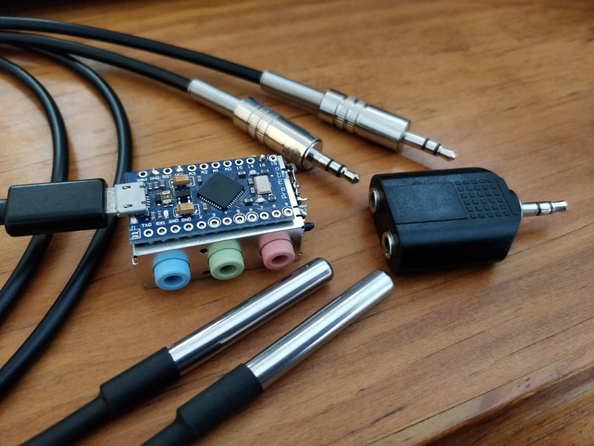
This is a “Pro Micro” Arduino Leonardo compatible board, connected to the DS18B20 sensors using 3.5 mm audio jacks. The benefits of these are that readily available plugs, sockets, splitters and extensions can be used. Don’t try plugging headphones in though, they will likely be fried!
Recipe
recipes/serial_temperatures_influxdb.config¶[datalogd]
connection_graph =
digraph {
a [class=SerialDataSource];
f [class=KeyValDataFilter, key="type", val="temperature"];
s [class=InfluxDBDataSink];
a -> f -> s;
}
Software
Download and install InfluxDB, and configure it to run at startup:
Download InfluxDB from https://portal.influxdata.com/downloads/ and unzip to
Program Files, then rename directory toInfluxDB.Go the directory and run
influxd.exe.Run
influx.exe. Typecreate database datalogdthenexit.Hit
Control+Con theinfluxd.exewindow.Get the InfluxDB.xml file and save it somewhere.
Open Task Scheduler (windows key, type
taskschd.msc, enter). ClickAction->Import Task..., select theInfluxDB.xmlfile. Click theChange User or Group...button, type your user name, clickCheck Names, thenOK.Right click the
datalogdentry, and selectRun, then clickOK.
Download and install Grafana:
Install.
Go to
http://localhost:3000, login withadminadmin, and set a new password.Add an InfluxDB data source using default settings.